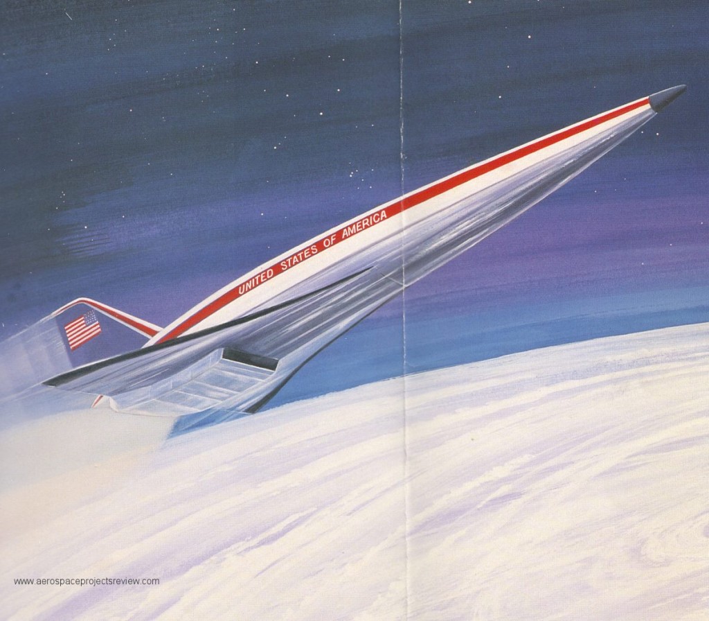
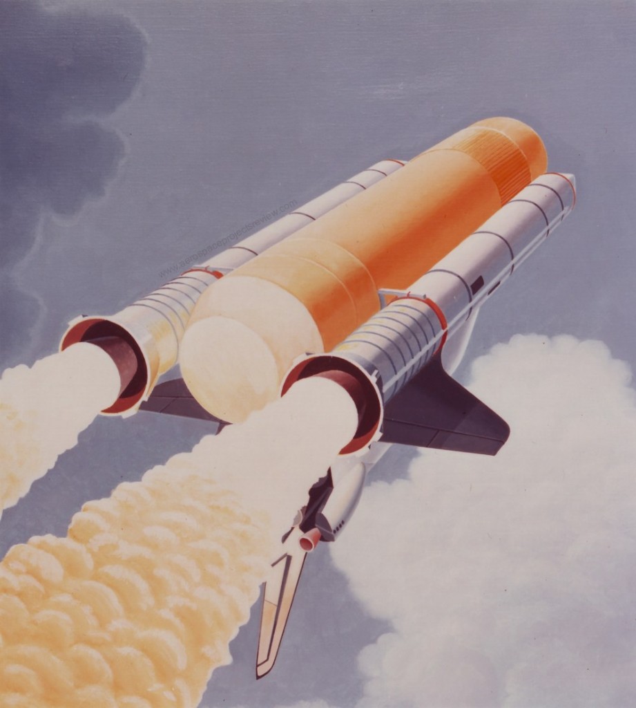
An artists impression of the National Aero Space Plane by United Technologies/Pratt & Whitney, ca. 1989. P&W was seeking to win the contract to build not the airframe, but the scramjet propulsion system. From a brochure found in the NASA HQ historical archive.
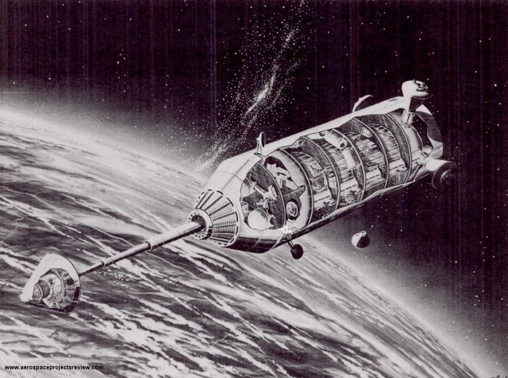
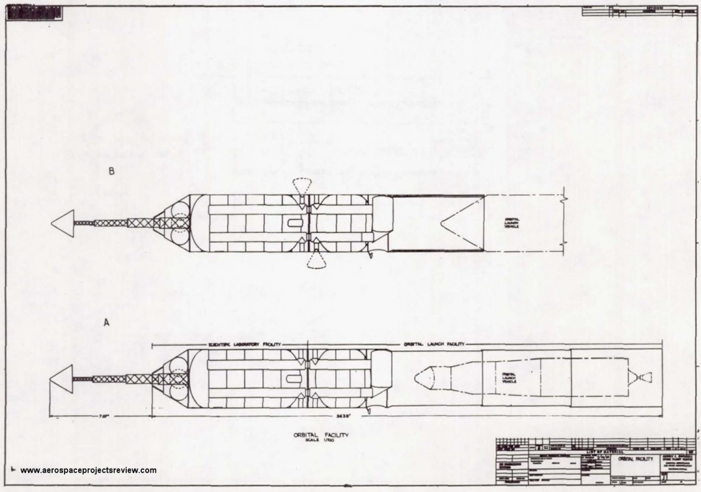
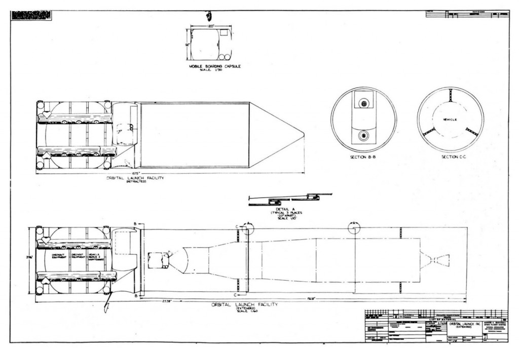
Designed in April of 1962, this NASA-Marshall Future Projects Branch design for a space station was to serve as both a scientific research facility and as an orbital launch facility (OLF). The research station concept is straightforward enough, but the OLF is more interesting.
At the time, it was just accepted that by the end of the decade Apollo would have proven successful… and was to have been merely the first step in the conquest of space. Lunar bases and missions to Mars would have followed soon on the heels of the Apollo program. To support these expected missions, the OLF would have served as a construction facility in space. Unlike many later orbital construction facilities, this OLF would have a telescoping hangar, providing a long cylindrical shield to protect the spacecraft and those working on it from excessive sunlight and micrometeoroids. Additionally it would provide a controlled lighting environment.
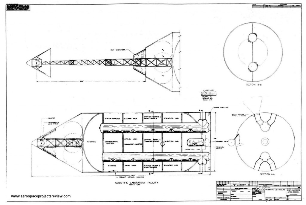
The facility would be launched in two components, each on a Saturn C-5 and both initially unmanned. The scientific research base would have a 30 kilowatt nuclear powerplant, and would be made from a Saturn S-IC liquid oxygen tank. The OLF would similarly use an S-IC LOX tank as a basis, and would dock to the scientific base once on orbit.
A 10-man crew would be needed for orbital launch operations, and a further 15 for the scientific base.
Scientific lab with reactor extended.
Diagram of assembled orbital launch facility
Scientific lab
Orbital Launch Facility
NASA has recently uploaded to YouTube an early video presentation on the NASP, showing the initial “du Pont” configuration.
[youtube 2bkZ2Sbsjp0]
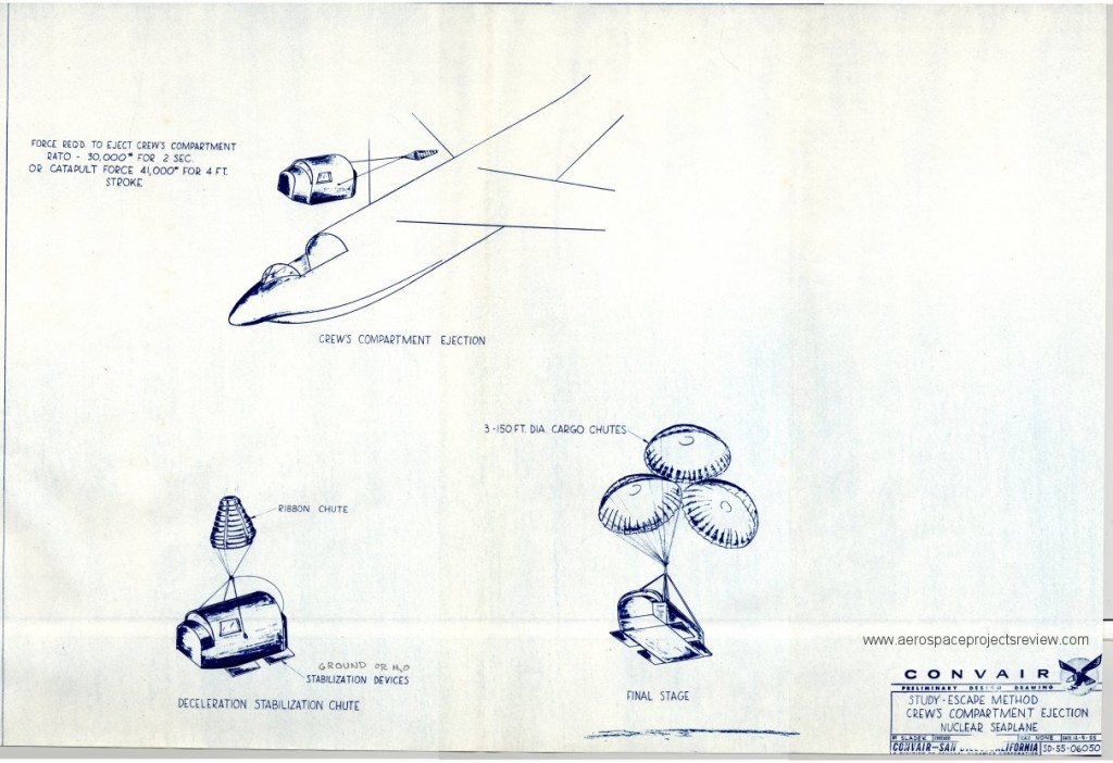
Because eventually your supersonic nuclear powered seaplane is going to fail, you are going to need a way to bail out at speed and at altitude. Obviously ejector seats are out of the question… you’d get shot distressingly close to both the reactor and the radioactive exhaust. Additionally, punching a hole in the massive lead cockpit shield big enough to get an ejector seat through *without* torching the crew would be problematic at best. So, Convairs solution to the problem, as shown in this 1956 diagram, was to eject the entire cockpit as a capsule. This is similar to the method used on the F-111 and the B-1A.
Note that the three parachutes are shown hilariously out of scale.
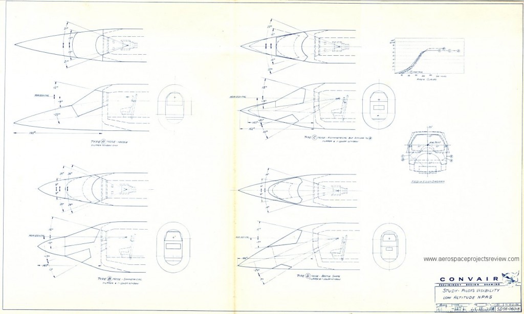
Several conceptual layouts for cockpits for a supersonic nuclear powered seaplane from Convair, drawing in 1956. To protect the crew from radiation, the cockpit was surrounded by a massive lead-lined shield, and only a relatively small leaded-glass transparency was provided for the pilot to see through. To minimize what was necessarily an enormous mass, the shield and transparency were flat and un-aerodynamic; the aircraft needed aerodynamic fairings around them. Easy enough except that the pilot needed to be able to see through those as well. So very large secondary windscreens were needed. Several possible layouts were examined and are shown below.
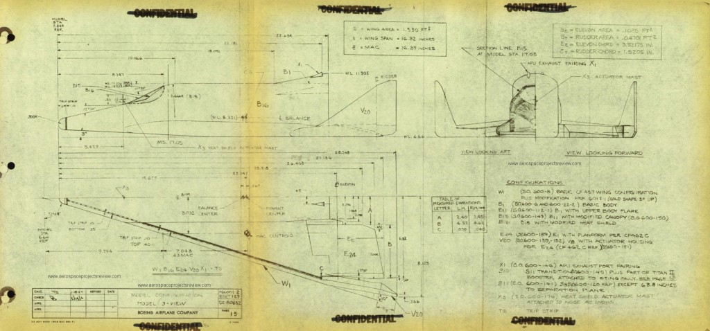
A 1962 Boeing diagram of the Model 844-2050 Dyna Soar configuration (almost the final configuration) as a 0.0666 scale wind tunnel model. Nothing too spectacular, but it does illustrate one detail rarely seen: the heat shield actuator mast.
The forward-facing windows were covered with an ejectable heat shield on the Dyna Soar until well after re-entry in order to protect them from excessive heating. The actuator mast would be a piston that would raise the front of the heat shield after the spaceplane had re-entered and slowed to subsonic; the “wind” would then get under the shield and lift it away from the spaceplane. I’ve seen very little on this mast… I don’t know if it would then retract, or if it would simply stay in place through landing. None of the artwork I’ve seen has ever depicted it in any fashion… the heat shield is always there until it’s simply gone. Associated photos of the wind tunnel model do not show the mast.
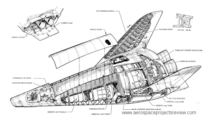
A cutaway diagram of a Boeing-Lockheed Space Shuttle concept derived from the Lockheed STAR Clipper design. This and other related concepts was covered in great detail in issue V3N2 of Aerospace Projects Review.
You can download a 1.5 megabyte version of this diagram; the link is HERE. To access it, you will need to enter a username and password. The username: the first word in the body of the text on page 8 of APR issue V3N2. The password: the first word in the body of the text on page 24 of the same issue. Note that both are case sensitive.
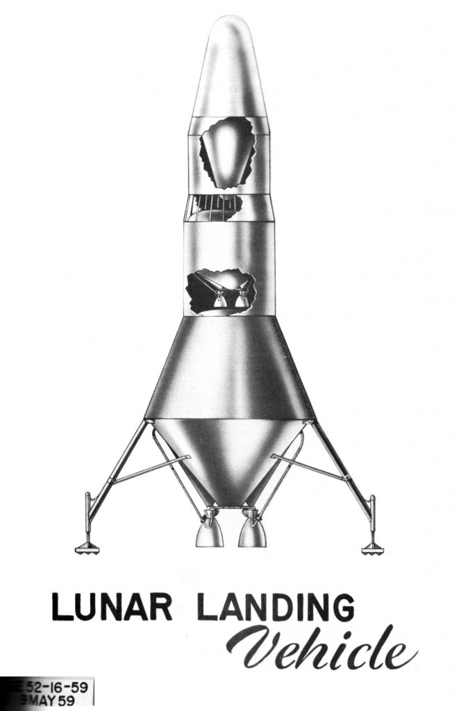
In the late 1950’s, before NASA was created, the USAF, the US Army and even the US Navy each thought that they might lead the American manned space program. The Army produced studies for Project Horizon, a manned Lunar base for military purposes (not just research and exploration, but also offensive nuclear capability). Horizon would have used early versions of the Saturn I to send men and equipment into space. To land on the Moon, large landers such as the one shown below would have been used. This multi-stage monster would have had the Earth return capsule up top (the downward-pointing cone inside the nose), a feature carried forward on early NASA Apollo concepts until Lunar Orbit Rendezvous became the baseline.
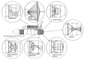
The Space Shuttle system was seemingly designed for modularity… the orbiter could be replaced, the boosters could be replaced. Payload shrouds could be placed alongside the tank in place of the orbiter, or on the nose of the external tank either replacing the orbiter or supplementing it.
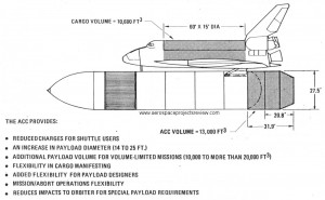
Martin calculated that the payload for the standard Shuttle using lightweight fiber wound solid rocket boosters and a lightweight ET going to a 215 nautical mile orbit would be 60,800 pounds. Payload to the same orbit would increase to 69,700 pounds if the ET was taken all the way to orbit (the more efficient SSMEs would be used all the way to orbit rather than relying on the OMS engines). By using the ACC and dragging the ET and ACC all the way to orbit, total payload would be 60,100 pounds.
A brochure from Martin Marietta describing the ACC is available HERE.
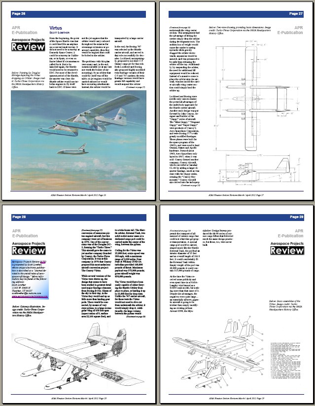
The Houston AIAA section has published a 4-page article I put together on the Conroy “Virtus,” a twin-fuselage heavy lift aircraft built from B-52 parts meant to serve as the Space Shuttle Carrier Aircraft. You can download it (in the March/April 2012 issue of Horizons) for free here:
