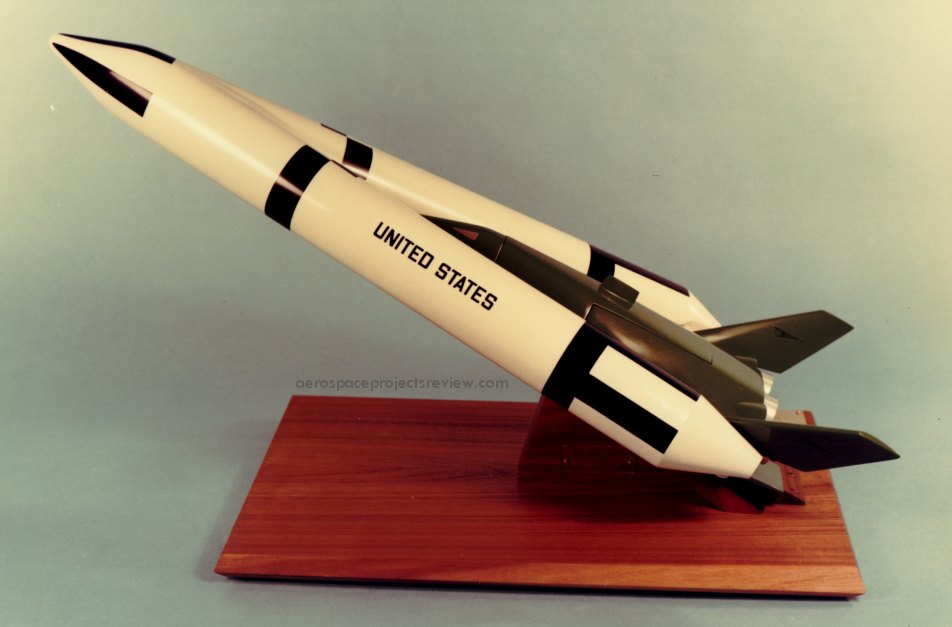
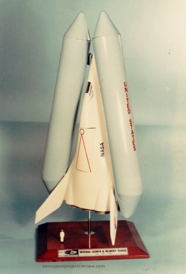
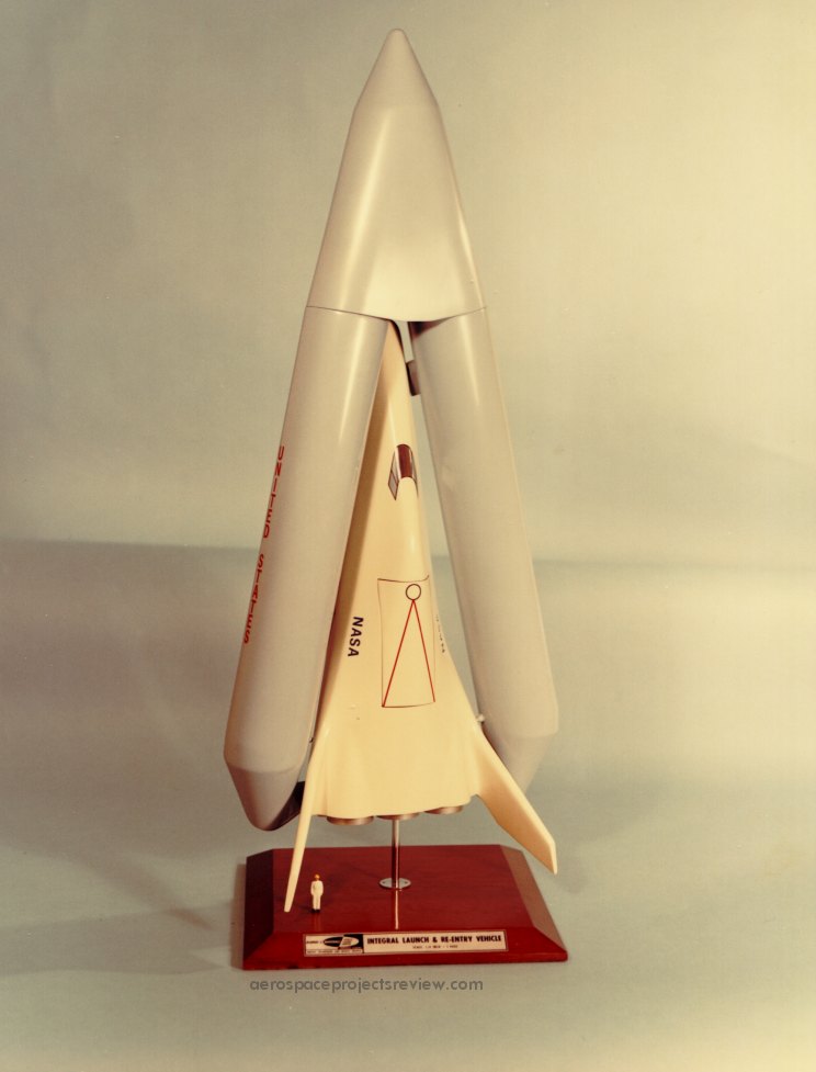
Another photo (via the NASA HQ History Office) of the Lockheed STAR Clipper. This was an early stage-and-a-half concept with a reusable orbiter and expendable propellant tanks. Vastly more info on this is available in APR issue V3N2.
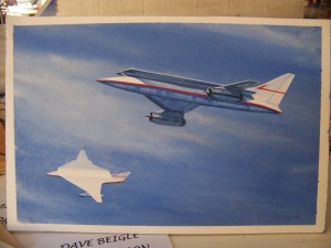
Someone is selling a McDonnell-Douglas painting (the original actual painting, it seems) of an SST concept:
The aircraft uses a “parasol” wing, which was a concept that enjoyed a bit of popularity in the 1970’s. The idea: at supersonic speeds shock waves shed from the nose of the craft would impinge on the underside of the wing, adding lift and reducing fuel requirements. As memory serves, an added bonus would be that the benefit of area ruling would be in place, but without the need to actually “wasp-waist” the fuselage. Being able to produce a bland cylindrical fuselage would greatly reduce cost and stress on the large pressurized structure.
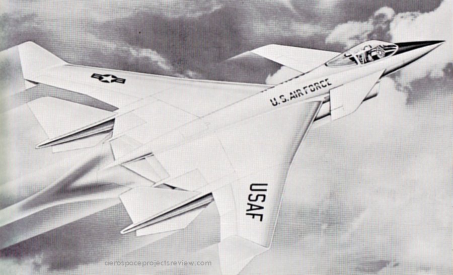
Such “favorable interference” designs would produced for fighters, SSTs and bombers, from USAF design labs to Boeing to McD to Lockheed and probably others. In time, the idea faded away; the gains in supercruise performance were apparently outweighed by cost and weight.
Note that the positioning of the engines, unusual for an SST, would also serve the favorable interference purpose: shock waves from the inlets would impinge on the wings above.
Another photo (via the NASA HQ History Office) of the Lockheed STAR Clipper. This was an early stage-and-a-half concept with a reusable orbiter and expendable propellant tanks. Note that this version does not have an aerodynamic fairing over the noses of the the propellant tanks. Vastly more info on this is available in APR issue V3N2.
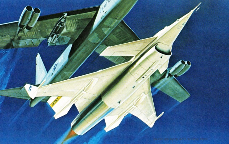
Rockwell artwork from the late 1970s depicting the launch of a HiMAT (Highly Maneuverable Aircraft Technology) subscale remotely piloted test vehicle from a B-52 carrier plane. While HiMAT was based on the design of a full-sized advanced fighter, it was a valuable program in its own right, demonstrating new structural materials (such as carbon fiber) and computerized flight controls.
A photo (via the NASA HQ History Office) of the Lockheed STAR Clipper. This was an early stage-and-a-half concept with a reusable orbiter and expendable propellant tanks. Vastly more info on this is available in APR issue V3N2.
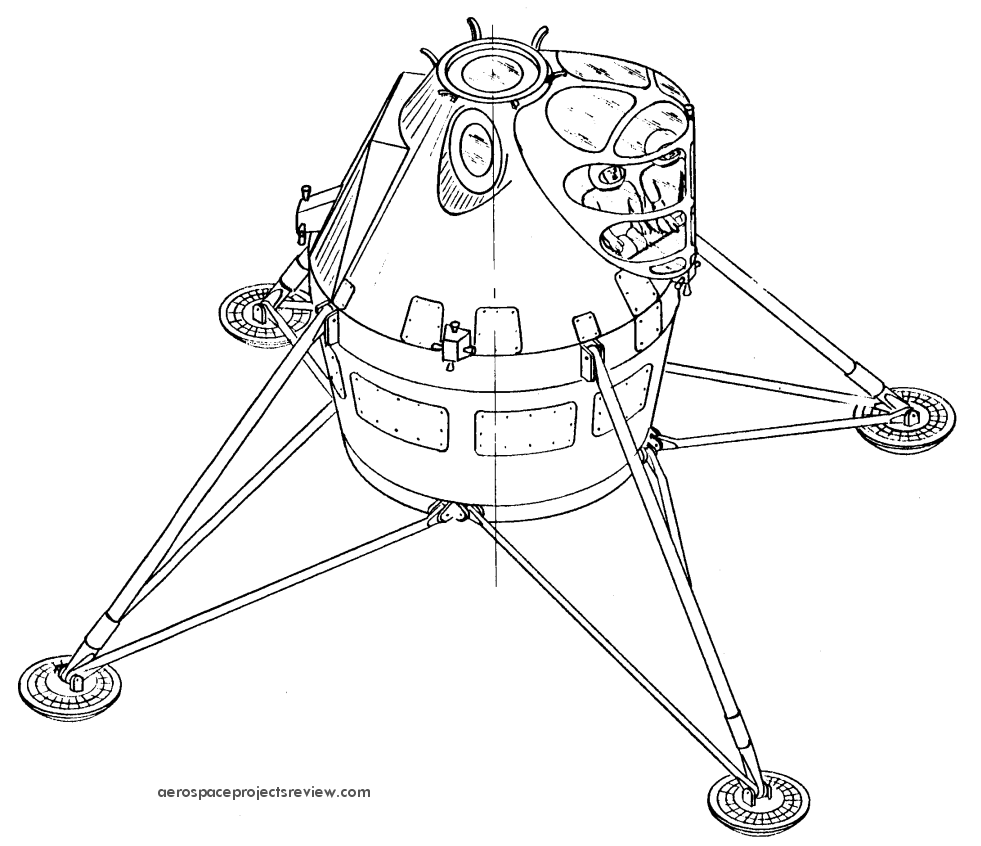
A modification of THIS design, with a raised canopy for the crew. This would greatly improve downward vision for landing. Note, though, that the crew are still seated at this stage in the design process. The size of the windows would mean a lot of excess mass, however.
Also note in the cross-section view that the toroidal propellant tanks are “tipped” by several degrees. This was not the case in the earlier design.
A color version of the art previously shown HERE.
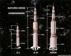
A 1962 NASA graphic showing the Saturn I, Saturn V and one or the more stereotypical of the Nova configurations to scale. Note that they all show direct-landing Apollo spacecraft… an extra stage, and no LEM. The Nova is similar to the “Saturn C-8” configuration. Note that the second stage of the Nova is larger in diameter and almost as long as the first stage of the Saturn C-5, and would have made the basis of a fairly substantial launch vehicle on it’s own.
