Feb 032013
 

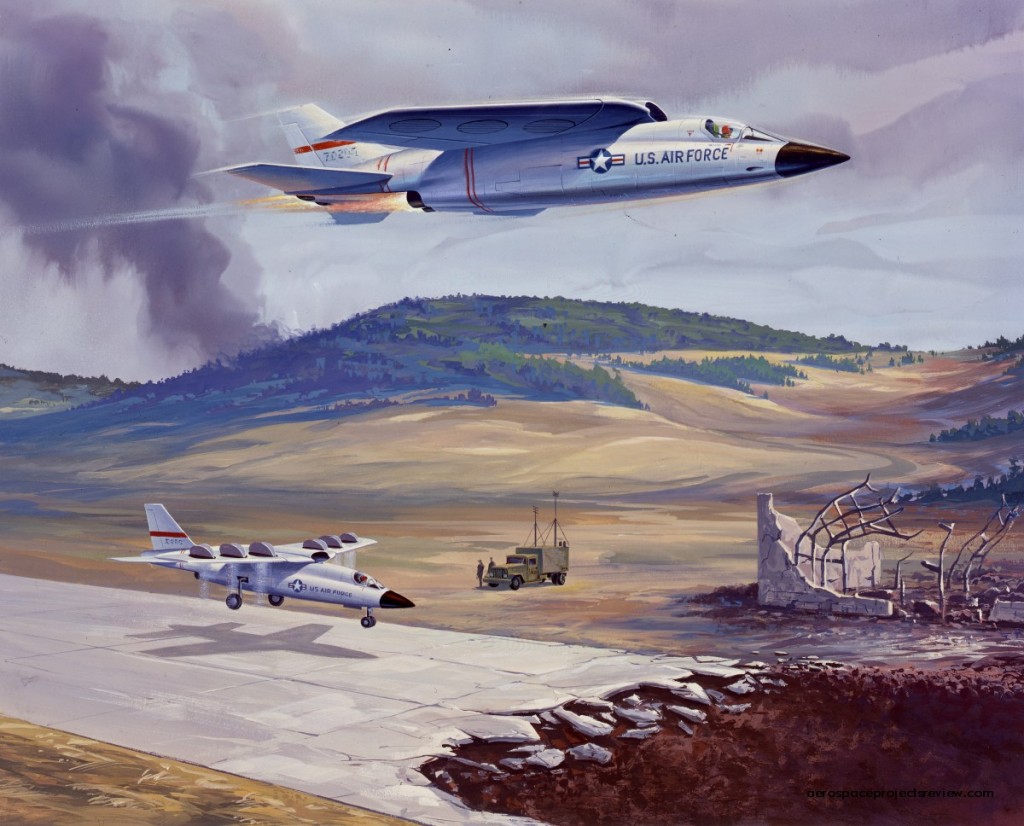
A piece of artwork from North American illustrating a vertical takeoff and landing aircraft. This was clearly intended for high speed… not only does it have four turbojet engines for forward thrust, if also have variable sweep wings. The complexity here is that the wings have embedded lift fans, probably driven be high pressure exhaust gas from two or more of the main turbojets. The ductwork would be impressive.

Role is unclear, but it appears to be a fighter or strike-fighter. Indications of weapons bays on the fuselage underside; at least one forward-firing gun. No other data available.

 Posted by at 11:40 am
Feb 012013
 

Long before the “Aurora” was flying across the pages of sensationalist magazines at Mach 6+, NASA was studying a range of hypersonic research aircraft. While the designs different, sometimes wildly, there were occasional configurations remarkably like the hypothetical “Aurora.” Some would argue that that means that the “Aurora” was derived from this earlier NASA work, but a more reasonable supposition is that those who envisioned “Aurora” were drawing upon public representations of the earlier NASA work in order to dream up what Aurora must look like.

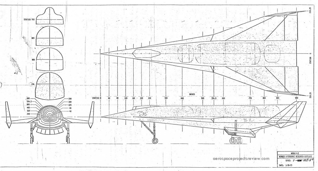
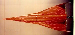
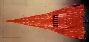
One such design that is very representative of the iconic “Aurora” image is this Hypersonic Research Airplane configuration from 1973, shown here as a drawing and as a NASA-Langley subsonic wind tunnel test model. The aircraft was powered by liquid rocket engines in the tail and an underslung scramjet pod. It had a cockpit that would raise up at low speed so the pilot could see to land, but was otherwise a very clean configuration.

 Posted by at 1:44 pm
Jan 292013
 

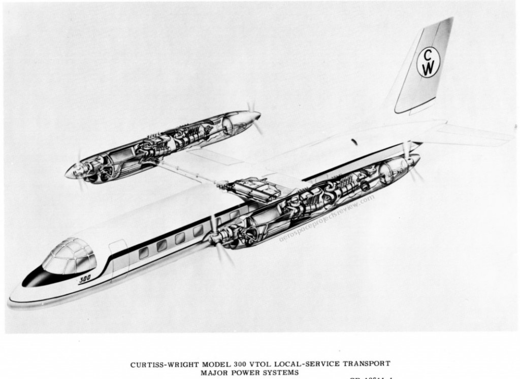
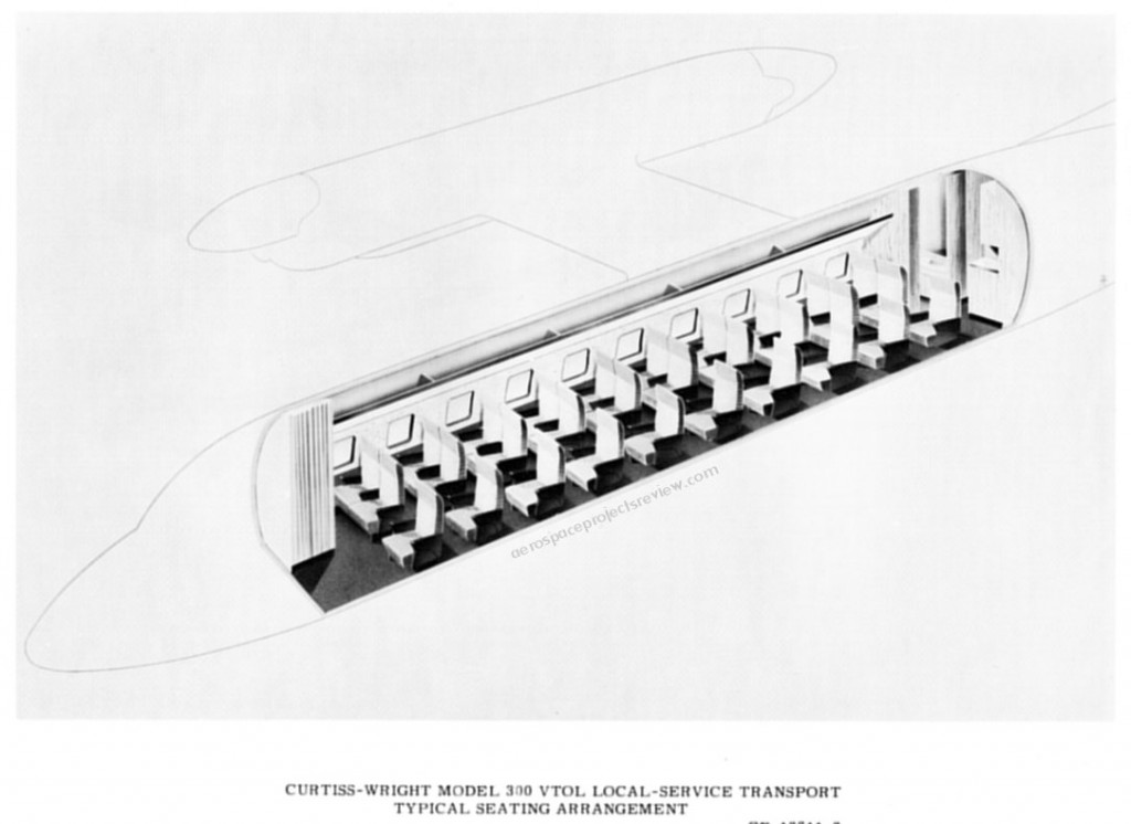
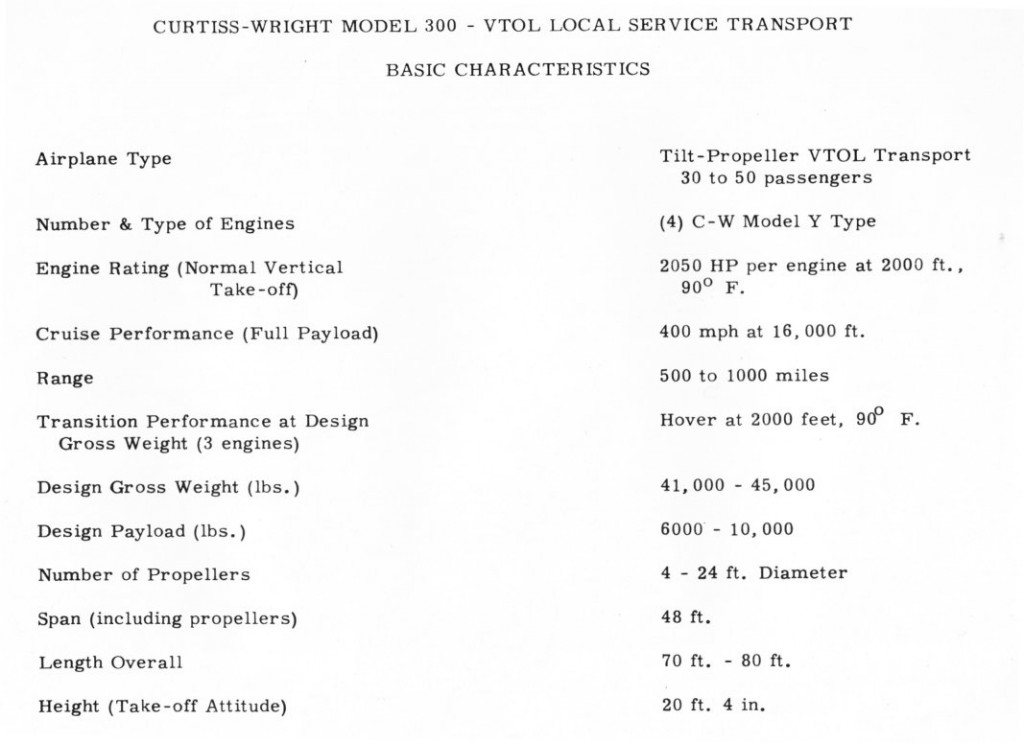
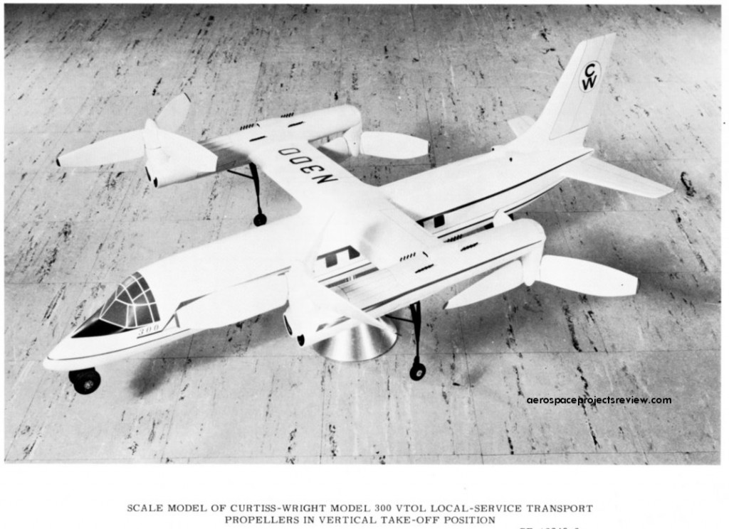
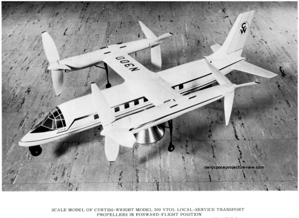
One of the last aircraft proposed by the Curtis-Wright company (early 1960’s), this version of the Model 300 featured a single main wing with wingtip engine pods. Each pod contained to Wankel rotary internal combustion engines; each engine drove a broad-bladed propeller (one at the front of the pod, one at the rear) of the type that had been successfully demonstrated on the Curtis-Wright X-19 VTOL aircraft. In order to attain vertical lift, the forward propeller would tilt up, the aft propeller would tilt down.

At the time, there was considerable interest in fast short-ranged VTOL transport. The idea was that small VTOL aircraft would operate from various small “ports” in and around major cities, flying to and from the nearest major airport (along with other transportation hubs). The VTOL would provide a bus service for the busy businessman on the go, who might need to leave his office in a hurry and catch the next jetliner to, say, London. While no VTOL aircraft such as the Model 300 were built and put into service for this role, several attempts to fill the “VTOL bus” role were attempted with helicopter, but due to noise and cost the concept never caught on.

 Posted by at 1:29 pm
Jan 202013
 

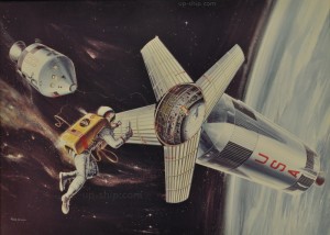
Found and photographed at the NASA-HQ historical archive was this painting depicting work being done upon an orbiting S-IVb stage. What’s happening is that small secondary payloads were to be installed in the Instrument Unit which ringed the top of the S-IVb stage below the conical main payload shroud, and they could be accessed by astronauts for use or retrieval. This is described in the Saturn V Payload Planner’s Guide (available HERE).

 Posted by at 9:15 pm
Jan 142013
 

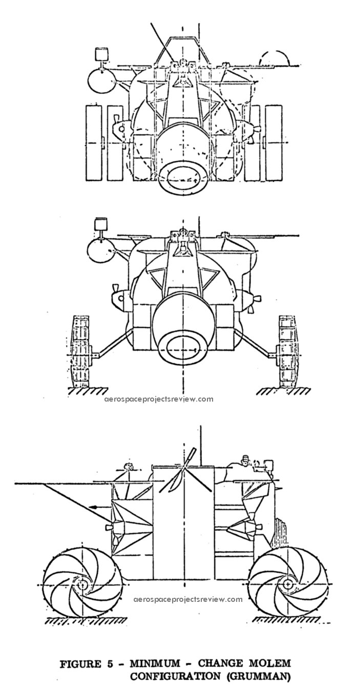
A 1966 Grumman concept for a long duration Lunar rover based on Lunar Module equipment, namely the crew compartment. Specifically, the cabin was from a Lunar Model derivative “lunar Shelter,” designed to land on the moon, but not to lift off again. By removing the rocket engine, propellant and other associated systems, a great deal of internal volume and payload mass would be made available. By mounting the cabin to a chassis with four wheels and 8 kilowatts of fuel cells, the MOLEM could provide a mobile shelter for two men for 14 days, permitting a total range of 250 nautical miles. Two 50 watt RTGS would be provided to power the MOLEM for up to 3 months after unmanned landing and the arrival of a crew. Other MOLEM drawings are HERE.

 Posted by at 11:28 pm
Jan 092013
 

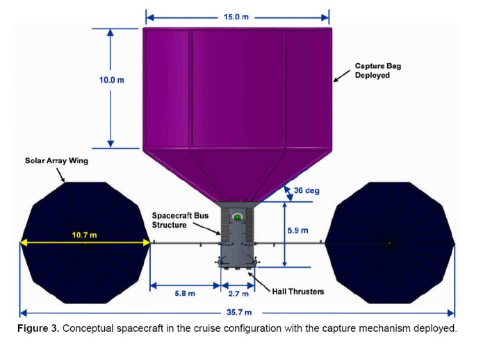
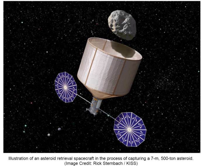
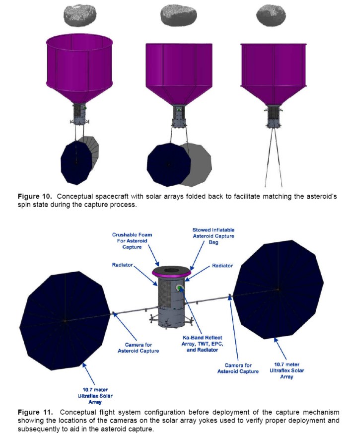
An interesting study written for the Keck Institute of Space Studies (at JPL) has been published describing how to go about grabbing a near-Earth asteroid of about 7 meters diameter (250 to 1000 metric tons mass), and drag it into Lunar orbit.

The spacecraft is proposed to be an unmanned vehicle with Hall effect thrusters (a type of ion engine), using large solar panels to generate the electricity needed. The writers of the study suggest that a 500-ton asteroid could be transported to high lunar orbit by 2025. The small asteroid could then be used as a base of operations/source of raw materials for manned missions to the Moon and beyond.

The capture mechanism would be fairly simple: a large inflatable bag. The spacecraft would simply envelope the asteroid (after matching rotation), cinch in the bag, and slowly shove the rock to the Moon. Due to the exceedingly low thrust/weight that the loaded spacecraft would have, lunar orbit capture would be a complex dance.

The spacecraft would have an initial mass of 18,000 kilograms and would be launched by an Atlas V or similar booster. The 40 kilowatt solar-electric propulsion system would have an impressive Isp of 3,000 seconds, but a vanishingly low thrust (which does not seem to have been given in the study). 12 metric tons of the 18 would be xenon propellant for the thrusters.

The mission would be a very long duration one. After being delivered to low Earth orbit, 2.2 years would be required to spiral out to the moon. A gravity assist would be used to boost the craft towards the target asteroid; 1.7 years would be needed for the cruise. After rendezvous, 90 days would be needed to precisely match orbits, precisely match rotation, capture the asteroid and de-tumble. Another 2 to 6 years would be needed to transit to lunar orbit. Total: 6 to 10 years. One example mission involves launch on 4/28/2018 and return with asteroid 2008 HU4 (assumed to be 7 m diameter, 1300 tons mass) on 4/26/2026.
 Posted by at 2:32 pm
Dec 302012
 

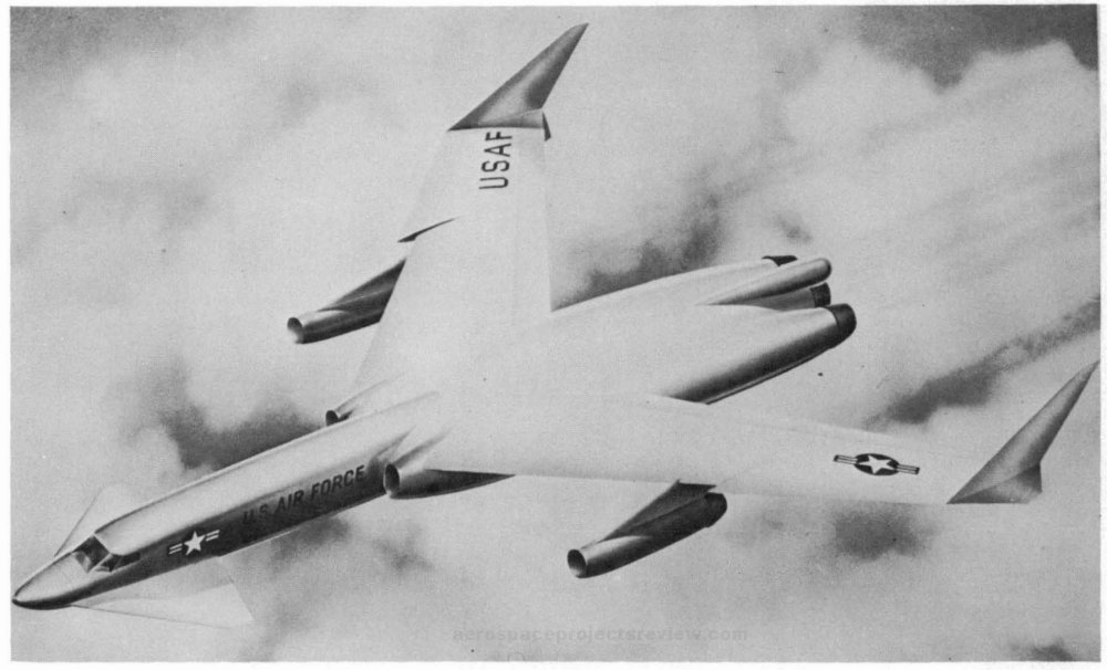
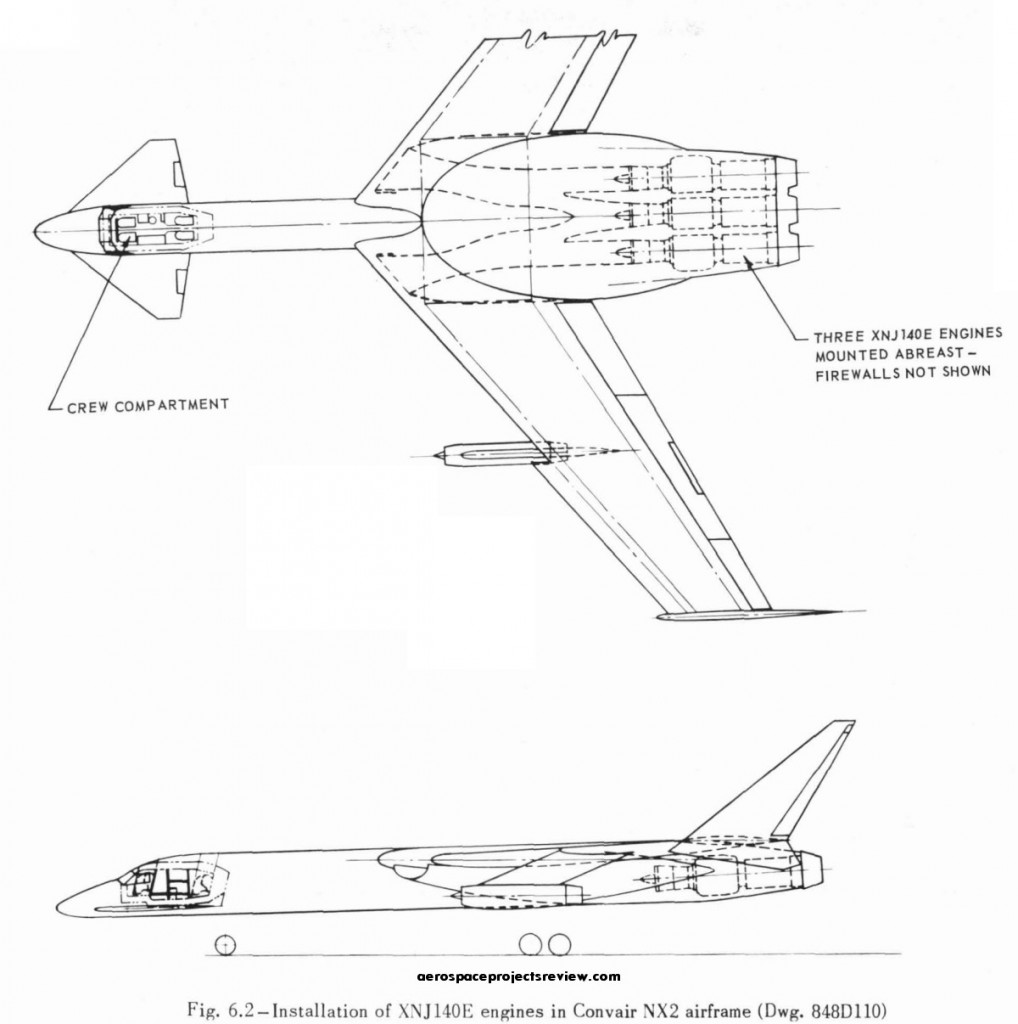
No point in developing a nuclear powered turbojet if you don’t have some sort of idea what you’re going to put it in. In the case of the XNJ140E, three of them were to power the Convair NX2. The NX2 was a research aircraft based on prior design work for a subsonic nuclear powered missile carrier, the Model 54 (not a “bomber,” per se, as it had no internal bomb bay and carried powered missiles rather than gravity bombs).

Numerous variants of the NX2 were designed, taking advantage of different nuclear turbojets. The design shown below used three XNJ140E’s to provide cruise propulsion; but for takeoff, two additional chemically fueled turbojets were provided in underwing pods.

The configuration was an unconventional canard layout. This had the advantage of letting the engines occupy the tail of the aircraft, clear of entanglements with wings or stabilizers. After landings the engines could be relatively easily removed from the aircraft for servicing and storage.

 Posted by at 4:29 pm