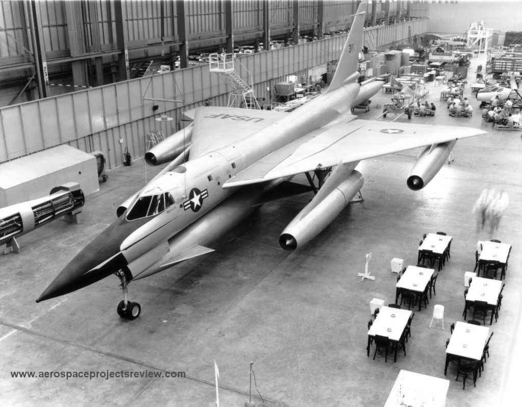
Following on the heels of the MX-1964 mockup was a mockup of the B-58 as it more or less was built. Clearly built in the same facility, what’s unclear from the photo is whether any components from the previous mockup were re-used. All the major components appear to be substantially altered, so it might have been an all-new structure, or it might have used some of the same internal supports. It would be nice if such things were able to be preserved, but mockups like this usually wind up getting turned into firewood.
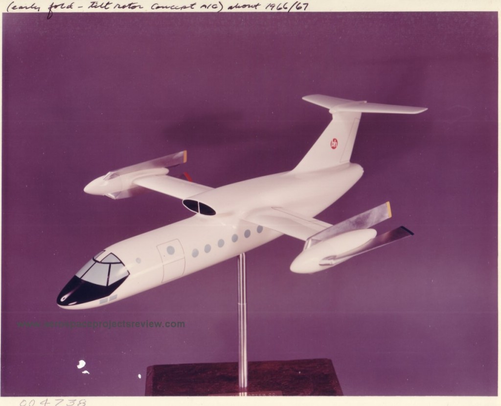
A photo of a Bell Fold-Rotor concept. The Fold-Rotor was a tiltrotor design that used the props for vertical flight and to get moving forward, but for high speed used other propulsion systems (in this case, the turboshaft engines mounted in the fuselage that drove the wingtip props would disengage and become straight turbojets), and the rotors would stop and fold back to reduce drag. It was an interesting idea, but it still had all the weight of a tiltrotor system, and then some, but with added complexity.
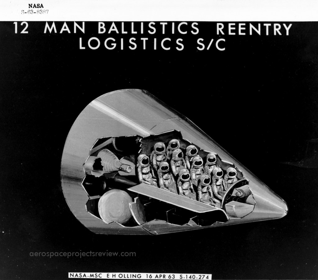
From the NASA HQ historical archive, a 1963 illustration of a large 12-man Ballistic Logistic System capsule. Such capsules were designed by NASA and various contractors to go atop Saturn boosters to provide crew and cargo transport to and from the large space stations that NASA fully expected to have in orbit in the early to mid 1970’s.
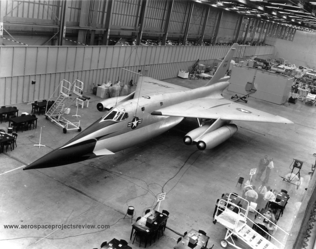
A truly gorgeous, and at first glance quite convincing, mockup of the MX-1964 predecessor design to the B-58. Note that this full-scale model is hanging from the ceiling by wires, much like many another model aircraft.
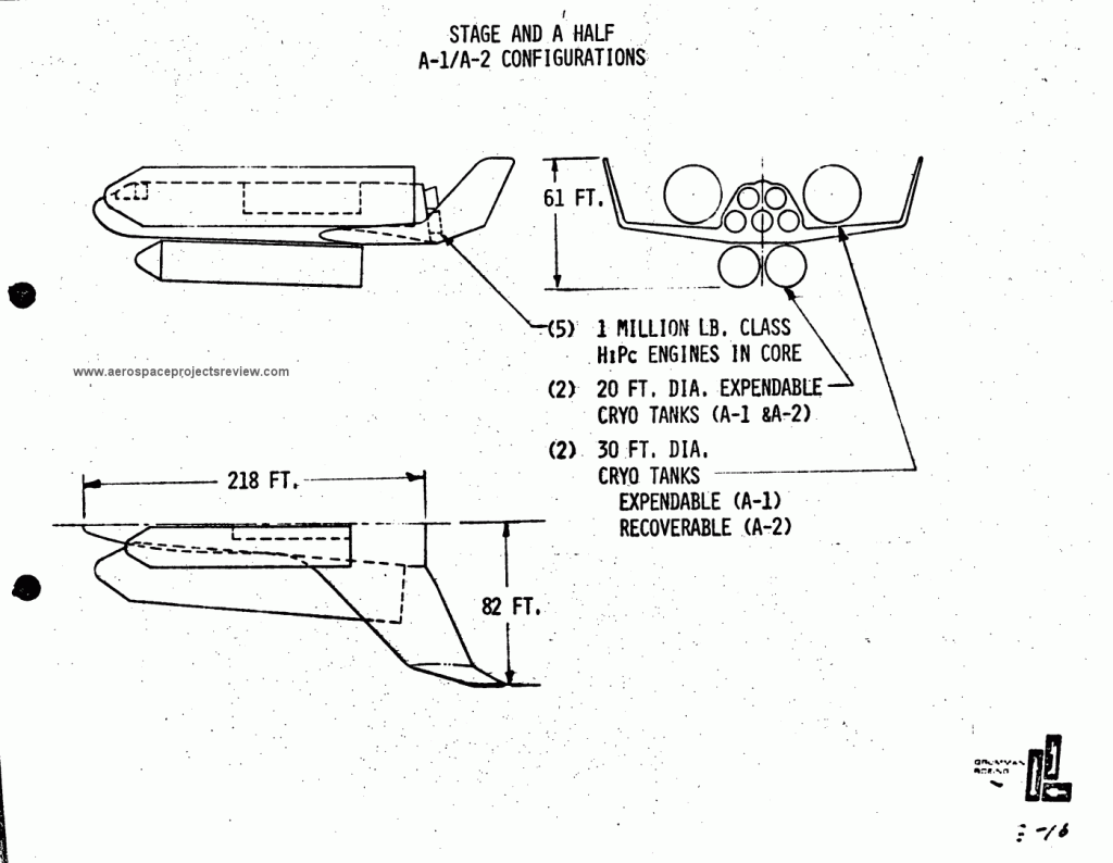
One of the more unconventional Space Shuttle concepts was this minor Grumman concept from 1971. Similar to the Lockheed STAR Clipper stage-and-one-half design, this design featured a fully reusable rocket powered spaceplane with expendable propellant tanks. Unlike the STAR Clipper, the Grumman design had four unattached tanks and a non-lifting body wing-body orbiter.
The Convair B-58 Hustler grew out of a long series of design studies dating back to the years immediately following World War II. Early concepts called for small jet bombers carried aloft by B-36 or B-60 bombers, and would shed jet engine pods during the mission. These massively complex and expensive systems evolved over time to the somewhat more straightforward B-58 which was a single stage aircraft carrying an underslung pod containing both jet fuel and a single nuclear weapon. But even that was originally intended to be a rocket powered missile.
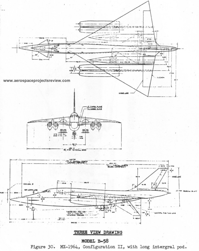
The B-58 evolved directly from the MX-1964 design from 1952. This is recognizably related to the B-58, but had the four jet engines in two pods rather than four, and a higher degree of integration between the pod and aircraft.
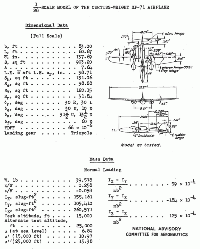
The XP-71 was a sizable Curtiss-Wright design from 1941 for a long range escort fighter. Irritatingly little has been publicly revealed about it. This is assuredly not due to the XP-71 being such an incredibly advanced design (although it was incredibly complex), but rather due to it having been a failed concept. Armed with two 37mm and one 75mm cannon, the XP-71 was bigger and substantially more expensive than a medium bomber such as the B-25, and would likely have been less nimble than a smaller fighter. While the armament would have packed a mighty whollop, targeting an Me 109 or a Zero would have been a matter of great luck or incredible skill. The XP-71 effort lasted from 1941 to 1943.
While I’ve recently been clued in on a Curtiss-Wright report with some good drawings of an oddly swept-wing version of the XP-71 (release of further info currently embargoed), very few decent quality drawings seem to have been released. One of the very few “official” three-views is a rather small diagram from a NACA report describing a great many spin-tests. I’ve not yet located the specific test reports dealing with the XP-71.
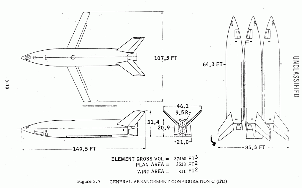
A 1969 Convair concept for a space shuttle. The Triamese used three vehicles that shared outer mold lines and many components… two as boosters, a third as the orbiter. The orbiter would have more complex rocket engines, featuring extendable nozzles for improved high altitude performance. All three included cockpits, relatively small high aspect ratio wings that would be stowed internally and flip out for landing, and flip-out turbofans for re-entry cruise and go-around capability. Numerous variants were studied including biamese versions using dissimilar boosters and orbiters.
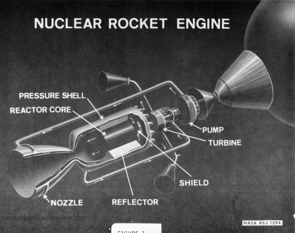
A 1963-vintage NASA illustration of the NERVA nuclear rocket engine. This is schematic only, depicting the main components of the nuclear engine. Not labeled are the two vernier thrusters; these take the otherwise wasted hydrogen exhaust from the turbopump and direct it more or less aft for some additional thrust. Further, they could, unlike the main engine, gimbal; this would provide a measure of thrust vectoring.
