Two pieces of NASA-marked (but likely not NASA-produced) concept art from the 1960’s depicted artificial-G space stations.
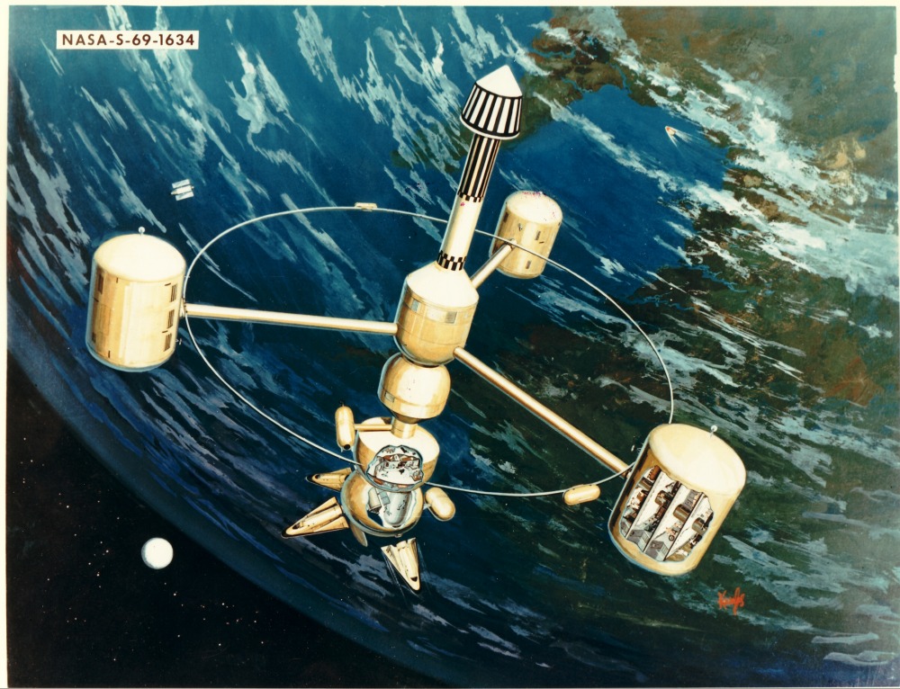
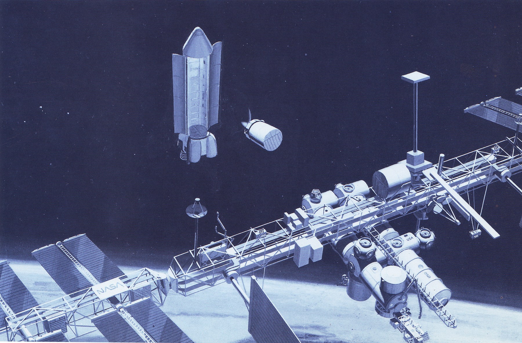
The first station (previously presented here in black and white not so long ago) depicts a substantial three-armed station witha multi-segment spine and three habitats. At one end of the spine is a nuclear reactor and its radiator; at the other end is a presumably rotationally0decoupled docking section. There is also an external “track” with two cars seemingly to provide transport from one habitat to another; it doesn’t really seem like this would provide a substantial improvement in transport over simply taking an elevator from one hab up to the spine and then down another elevator to the destination hab.
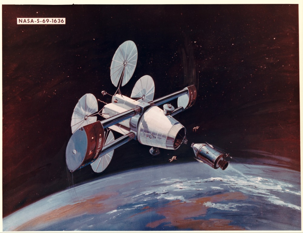
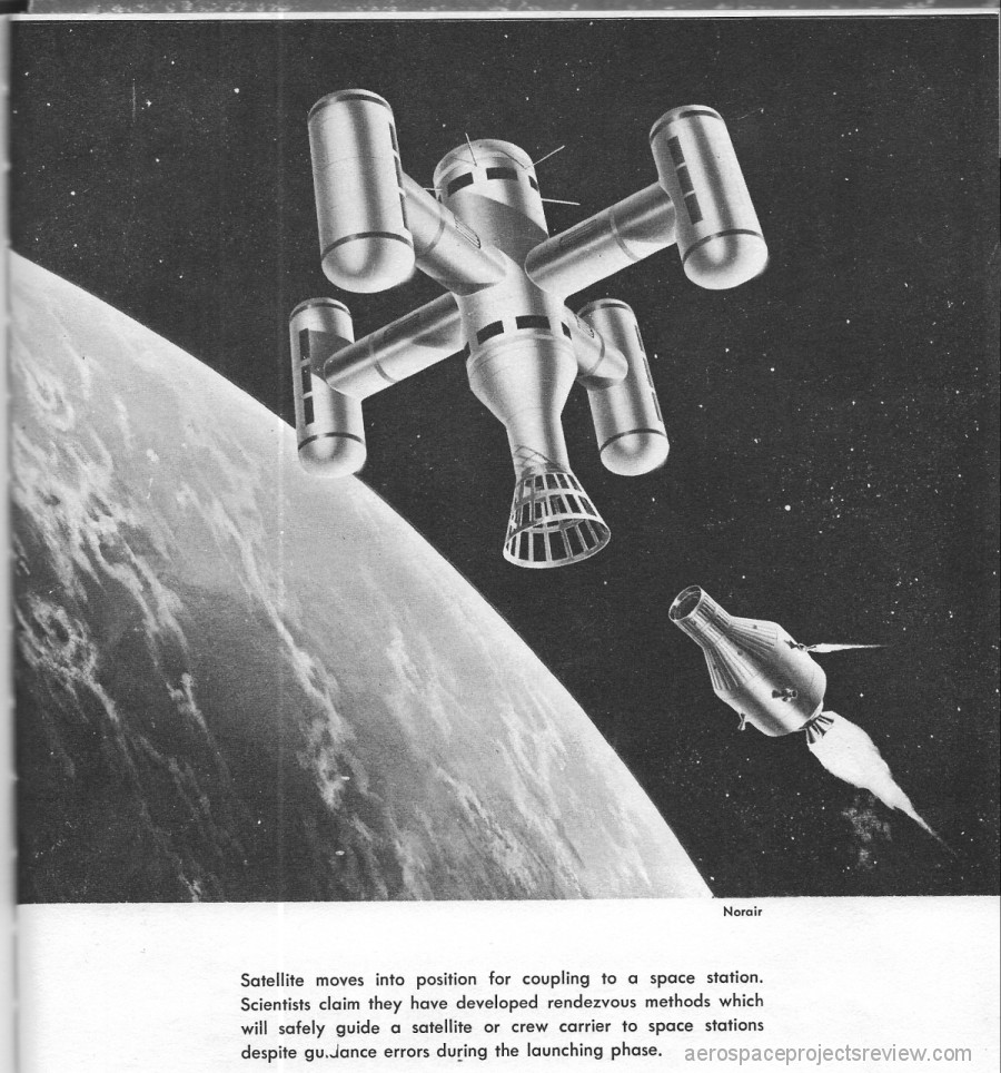
This space station, which appears from the art style to be a Grumman design, is a single-launch space station to be launched atop a Saturn V. The two arms would fold back for storage on the launch vehicle and would deploy once in orbit. An Apollo CSM is shown approaching for docking along the centerline; it’s not clear if the docking cone was rotationally decoupled. if it was not, the two Apollo-like capsules hanging off the sides of the cone are a bit of a head scratcher.
Both renderings have been uploaded in their full resolution to the 2019-01 APR Extras dropbox folder. This folder is available to APR Patreon Patrons and APR Monthly Historical Documents Program subscribers at the $4 per month level and above.