As well as the 11X17-format PDF collection of diagrams for USBP07 through 09.
———————————-
USBP 11
Issue 11 of US Bomber Projects is now available (see HERE for the entire series). Issue #11 includes:
- Boeing Model 464-40: The first all-jet-powered design in the quest for the B-52
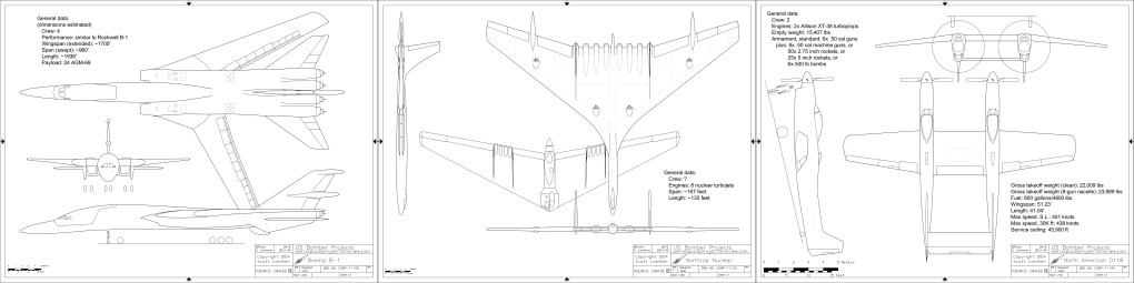
- North American D-118: A turboprop conversion of the F-82E into a ground attacker
- Boeing Model 701-218: A twin engined supersonic concept
- NAA Model 705-00-04: A ramjet cruise missile with a manned rocket booster
- Northrop Nuclear Flying Wing: A well defended if rather hypothetical design
- Martin Model 223-11: *almost* the XB-48
- Boeing B-1: The design that might have beaten the Rockwell concept
- Bell/Martin 464L: The submission that most closely resembled what the Dyna Soar eventually became
USBP #11 can be downloaded as a PDF file for only $4.25:
——–
———
USTP 01
And also available, issue #01 of US Transport Projects. Done in the same format as US Bomber Projects, USTP will cover flying vehicles designed to transport cargo, passengers and troops. Issue 01 includes:
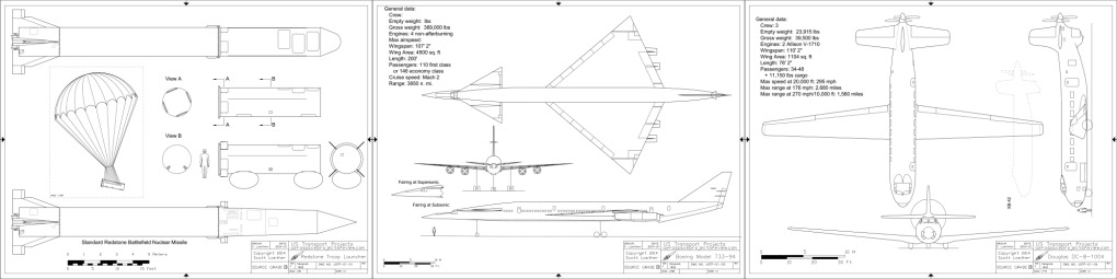
- Redstone Troop Transport: An Army concept for a troop & supplies launcher
- Lockheed CL-334-1: A small STOL battlefield transport
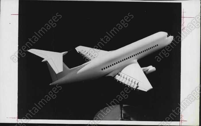
- NASA LH2 747: A “three fuselage” hydrogen-fueled jetliner
- Douglas DC-8-1004: A very clean pusher-prop passenger liner
- Bell/Boeing/NASA ATT: A wasp-waisted transonic concept
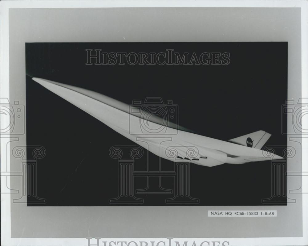
- Boeing Model 733-94: An early SST
- Aereon Dynairship: A giant modern airship
- Boeing Model 473-10: One of the earliest jetliner designs
USTP #01 can be downloaded as a PDF file for only $4.25:
——–
———
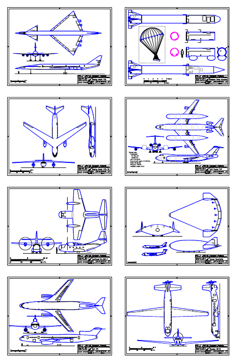
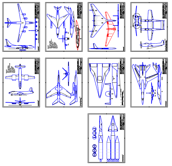
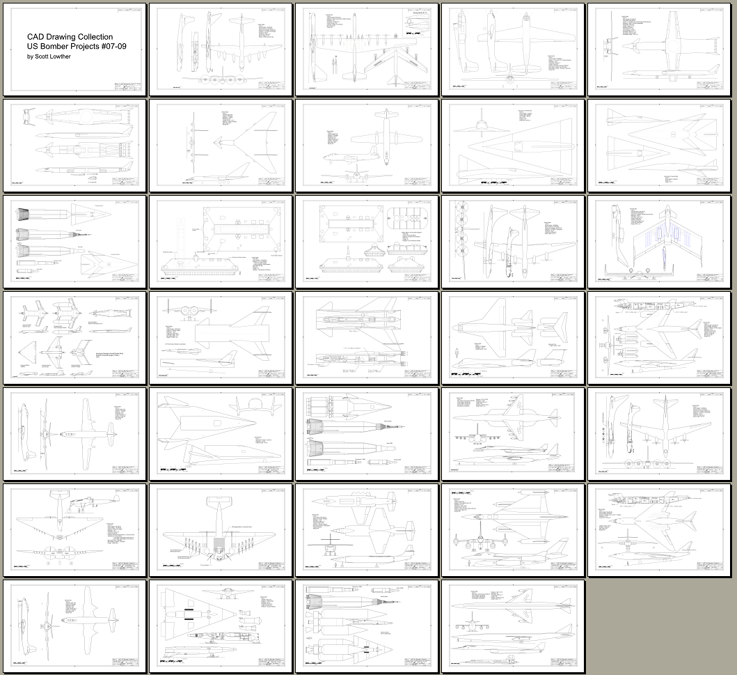
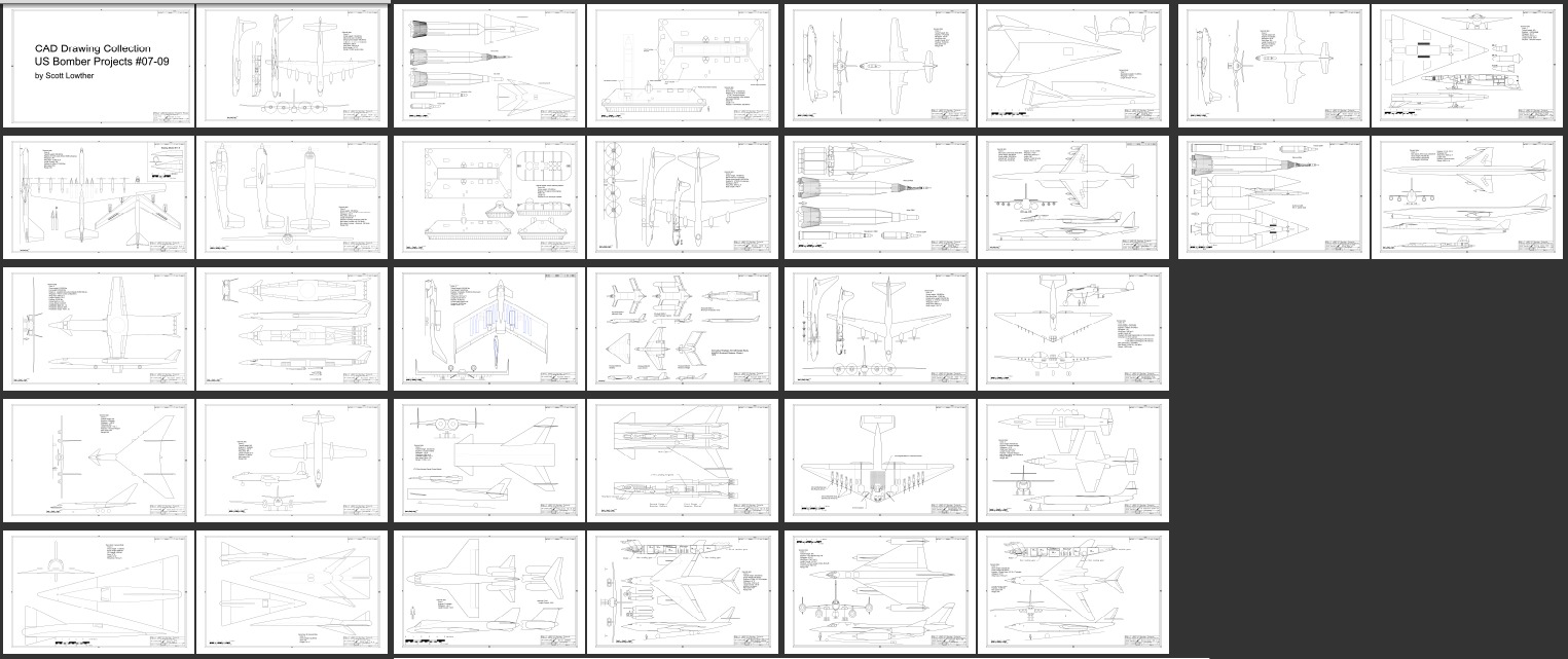
Large format USBP drawings, Issues 07-09
The CAD drawings created for USBP reformatted and rescaled for 11X17 collected in a separate volume. Drawings have in some cases been corrected, improved and added to.
USBP 11X17 07-09 collects the diagrams created for issues 07, 08 and 09, including:
Boeing model 464-25; Boeing Model 828-2; Fairchild N-12; Rockwell D645-3; Boeing Model 701-273-7; Martin Model 223-7; Convair 464L Dyna Soar I; Convair 464L Dyna Soar III; Bell MX Hovercraft; Bell mobile defense platform; Boeing Model 464-27; Rockwell D645-6; Republic M-4.25; Martin MAMBA; Boeing Model 484-2-2 (twin-pod); Martin Model 223-8; Douglas 464L Dyna Soar I; Boeing Model 800-11A; Boeing Model 464-33-0; Consolidated Army Bombardment Type; GE Supersonic System 6X; Convair B/J-58 B-58C; Boeing Model 484-2-2; Martin Model 223-9; Northrop N-206 Dyna Soar I/II/III; Boeing Model 800-15A
USBP11x17-01-03 can be downloaded as a PDF file for only $11:
————–
———