A North American Aviation artists impression of a supersonic transport derived closely from the B-70 Mach 3 bomber. An article on this concept by Dennis R. Jenkins was published in Aerospace Projects Review issue V2N1.
A North American Aviation artists impression of a supersonic transport derived closely from the B-70 Mach 3 bomber. An article on this concept by Dennis R. Jenkins was published in Aerospace Projects Review issue V2N1.
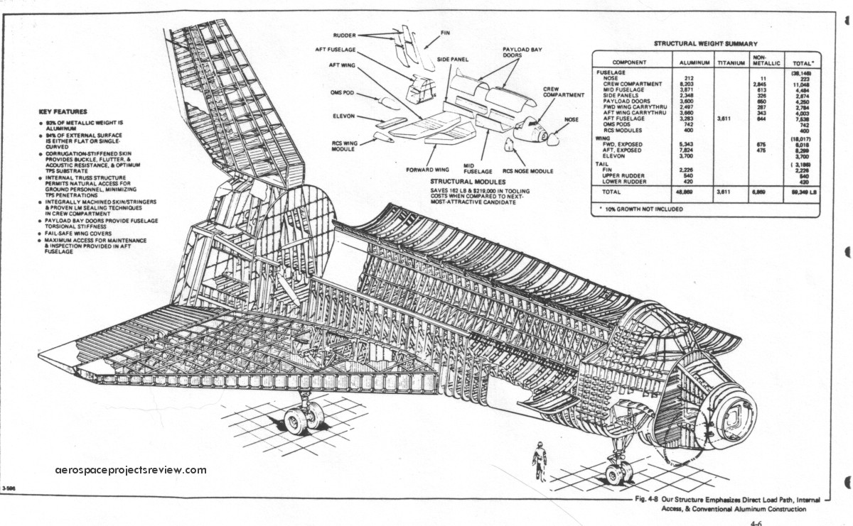
Some of the design features of the Grumman Design 619. Compared to the Shuttle Orbiter as actually built, the most obvious difference is the inclusion of the air breathing propulsion system model that consumes about 1/3 of the payload bay. Also note the RCS modules on the wingtips, the outward-bowing payload handlers station, nose airlock and the solid abort rockets along the aft fuselage.

Proposal artwork depicting the interior structure of the Design 619 space shuttle concept. Note that the airlock, used for docking to space stations and the like, is in the nose.
A little-known and poorly-documented proposed variant of the Titan family of launch vehicles, the Titan IIIG used an increased-diameter core with 156-inch diameter solid rocket boosters. The late-1960’s Titan IIIG would have been capable of launching 100,000 pounds, and seems to have been focused on USAF missions. McDonnell Douglas appears to have considered it for use in launching the Big Gemini logistics capsule. Beyond that, not much is known. The McD illustration below is one of the few I’ve come across, and does not seem likely to be terribly accurate. Also depicted here are the Titan IIIM, a launch vehicle composed of a cluster of four 156-inch solids topped by an S-IVb stage (a McD product), a 260-inch solid topped by an S-IVb, and external tank arrangements for reusable launch vehicles such as the ILRV (integral Launch and Recovery Vehicle), a predecessor to the Space Shuttle. McD’s entry to the ILRV study was a derivative of their generic Model 176 concept.

A NASA illustration of the first stage of the Saturn C-5, from very early 1962. It is more or less what the S-IC stage became, except for much larger stabilizer fins and separation rockets located up front, rather than in the engine fairings.

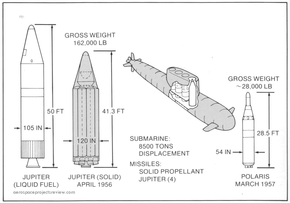
Before the Polaris missile was developed, the US Navy studied several approaches to using submarines to launch ballistic missiles. An early idea was taken directly from WWII Germany… store Jupiter IRBMs in special canisters, towed behind subs. These would be partially flooded whe the subs got to the launch site; this would cause the canister to tip up 90 degrees. A few hours later, the liquid fueled Jupiter would be ready to launch. Additionally, there was some thought put into the idea of installing the Jupiter vertically within subs. But nobody much liked the idea of large liquid propellant missiles in submarines. So by April 1956 the idea then moved to solid propellant rockets designed to emulate the Jupiter, carrying the same payload on more or less the same trajectory. The missile would be fatter than the standard Jupiter, but also shorter. Still, at ten feet in diameter and 41 feet in length, it was a very large missile, and only four could be carried within the body of the sub and the greatly extended sail. Fortunately, within a few months the Polaris design came on the scene, a much smaller missile made possible by both a smaller warhead and higher energy density double-base solid propellant.
Lockheed illustration.
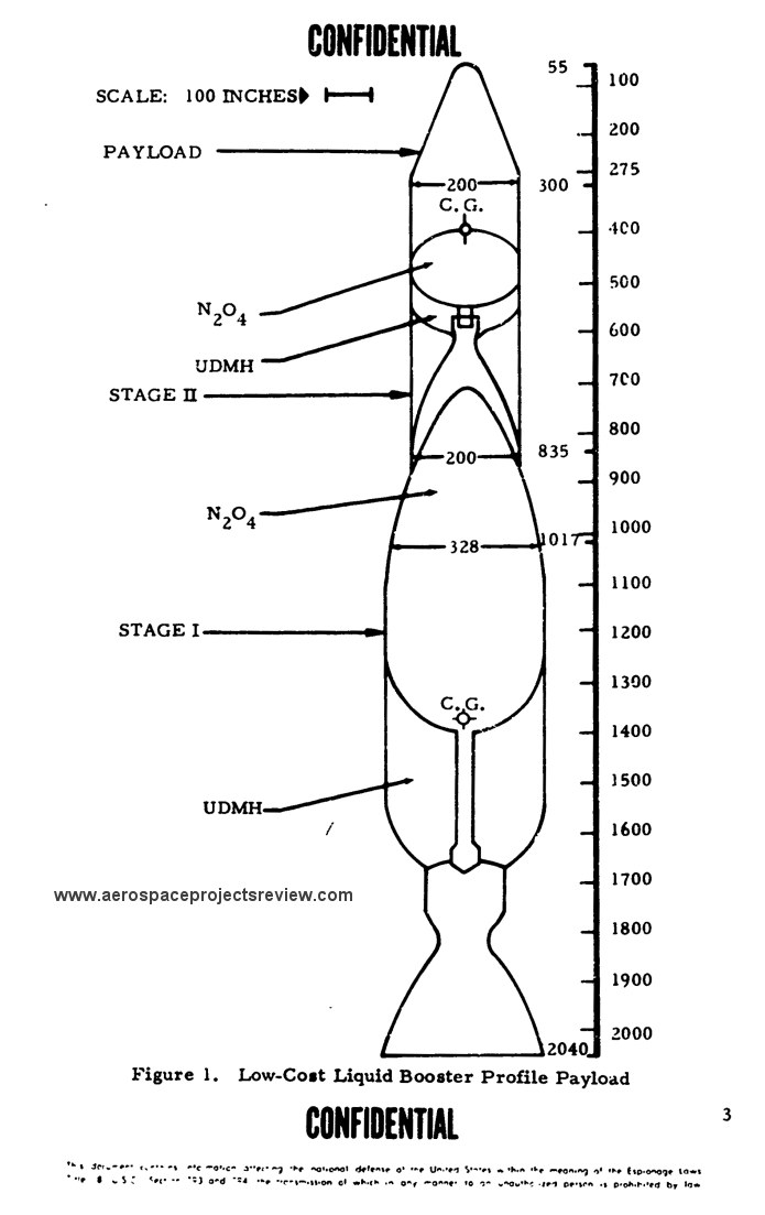
In the late 1960s, prior to the Shuttle concept really taking off, the USAF funded studies of low cost boosters. One type that received considerable study was a two-stage pressure fed layout. This was vaguely similar to the earlier Aerojet Sea Dragon in that it would be a heavy and simple design, using shiplike construction and dense propellants. The nature of the first stage booster was such that recovery was anticipated. Propellants were hydrazine and nitric acid.
A trio of NASA-Marshall heavy lift launch vehicle concepts, circa 1985. The first two configurations used a clustered booster stage; the third configuration used series staging, with a unique feature than the booster stage had no LOX tank, only a kerosene tank. The LOX for the first stage was contained within the second stage. This would make the vehicle more complex, but it would also make the first stage more recoverable.

The three designs were designed for the same mission, launching 300,000 pounds to LEO (specifically a 100X540 nautical mile transfer orbit, with circularization at 540 n. mi. to be performed by a kick stage). All three used an all-new LOX/kerosene booster engine, the Space Transportation Booster Engine, slightly more powerful than the F-1. All three used a new LOX/LH2 upper stage engine, the Space Transportation Main Engine, on the core vehicle. The STME used an extendable nozzle for good performance at both low and high altitude.

The selected configuration was #2:

The boosters for Configuration 2 were independently recoverable. The five STMEs for the core stage were contained in a recoverable propulsion & avionics module, which would splash down for recovery, refurbishment and reuse.

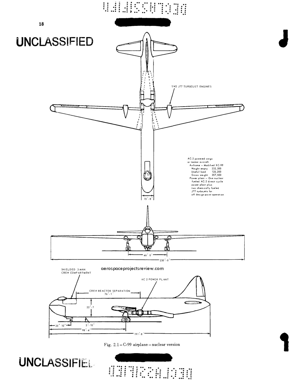
A 1953 General Electric study for a Convair C-99 cargo plane modified with nuclear turbojet propulsion. The pusher-prop engines were removed from the wing and replaced with a 65,000-pound AC-2 nuclear powerplant within the fuselage. This was equipped with two separate jet engines, giving a total sea level static thrust of 35,500 pounds. Two additional conventionally fueled J77 engines were mounted in the wings for takeoff thrust. A lead and polyethylene shielded crew compartment weighing 20,000 pounds protected the crew, giving radiation doses of 0.5 roentgen per hour.
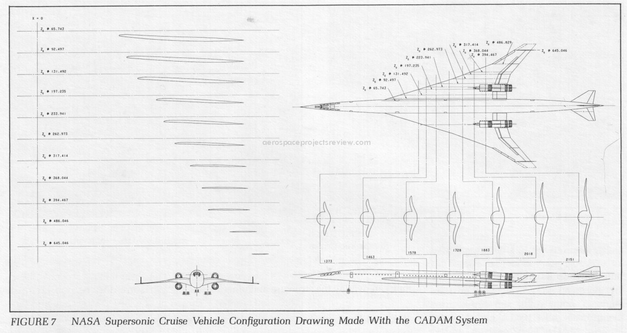
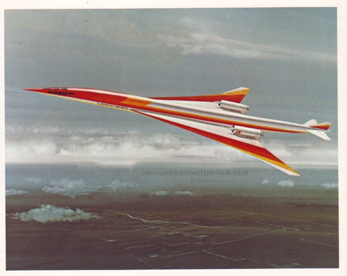
A late 1970’s/early 1980’s design for a supersonic transport from Lockheed included an unusual engine layout… two turbojets on the underside, two turbojets on the topside. This would certainly prevent shockwaves from the inlet spike of one engine from interfering with the inlet of another nearby engine, but it would also make the engines on the topside somewhat questionable during high-alpha (angle of attack) flight, such as takeoff and landing. Note that the drawing wa made with an early CAD program.